What is Multi Column Chromatography?
Primary chromatographic capture is one of the main bottlenecks in downstream bioprocessing both in terms of time and cost. Several technologies to intensify capture chromatography are being developed to create a more intensified, efficient, and potentially continuous bioprocess. In this article, we will discuss one of the methods used to intensify the capture chromatography process: multi column chromatography (MCC).
Read more about
- Batch Chromatography vs. Multi Column Chromatography
- Advantages of Multi Column Chromatography
- Case Study: Integrating MCC into a Continous Downstream Process
Batch Chromatography vs. Multi Column Chromatography
In traditional batch chromatography, the product is loaded into one column, washed, and then eluted for further processing. The resin in this column is typically not used to its full capacity to prevent product loss during breakthrough. To prevent unacceptable product loss the dynamic binding capacity (DBC) of a capture resin is determined during development as a mere 5% or 10% of product breakthrough. In manufacturing, the column is then loaded to 80–85% of this DBC, which then corresponds approximately to only 60–70% resin utilization. All operations (loading, washing, elution, etc.) are performed on that single column, with the product flow halting during the non-loading steps like regeneration, washing and elution.
In contrast, multi column chromatography uses smaller columns that are placed in series. In MCC the product is loaded onto the first column and the breakthrough is captured directly onto the second column (Figure 1, Step 1). Once column 1 is saturated the feed switches to directly load column 2 which then breaks through onto column 3. Whilst the loading of column 2 takes place, column 1 is washed, eluted, and regenerated (Figure 1, Step 2). Once complete and column 2 is saturated, it cycles so column 2 is washed, eluted, and regenerated. Column 3 directly loads the breakthrough onto the newly cleaned and equilibrated column 1. (Figure 1, Step 3).

Figure 1.Multi column chromatography workflow. MCC allows the simultaneous loading, wash, elution and regeneration of multiple columns.
This complete sequence is called a cycle and can be repeated as many times as necessary to process all material or until the validated maximum number of cycles is reached on the chromatography resin.
Advantages of Multi Column Chromatography
There are three key advantages to implementing multi column chromatography:
- Reduced resin requirements. More complete utilization typically reduces resin requirements by 20%, process, product and resin dependent.
- Capability to run continuously with minimal surge tankage.
- Rapid cycling capability. In early clinical phase material production, only a fraction of total cycle life time is used on the Protein A resin as the campaign product needs are restricted. MCC allows you to increase the number of cycles used in a single batch to better leverage resin reuse rates.
Case Study: Integrating MCC into a Continuous Downstream mAb Process
Objective
The objective was to connect and run a complete continuous downstream process in order to demonstrate benefits such as reduced costs, increased productivity, and lower environmental impacts. This was proven by executing four process runs at ~1000 L bioreactor scale with a titer of ~4 g/L of mAb. The objective of the capture step was also to demonstrate the possibility to capture mAb continuously and robustly with the multi-column capture system.
Materials and Methods
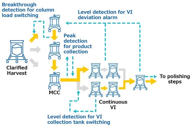
Monoclonal antibodies were produced in a 1000 L bioreactor, operated in fed-batch mode. Cell culture harvest was pre-treated with pDADMAC® cationic polymer flocculant and clarified through Clarisolve® 40MS depth filters followed by Millipore Express® SHC sterilizing-grade filter. This clarified pool was continuously loaded onto Protein A Resin (3 x 0.55 L, 10 cm Ø x 7 cm BH) utilizing the multi-column capture system at an average flow rate of 0.28 L/min for 2.5 days. The elution peaks were continuously sent to viral inactivation. The viral inactivation skid (VI) was composed of 3 L single-use tanks with the capacity to continuously decrease the pH, hold the solution for the desired time, and re-adjust the pH prior to polishing. Product was then polished in flowthrough mode and sent to subsequent operation. All continuous operations were performed using interconnected systems (Figure 2) in order to trigger process actions and send feedback alarms in case deviation occurred. Post-column UV sensors triggered the switch between loading columns based on a breakthrough detection and the switch between waste and fraction during elution peak detection. A valve was installed on the inlet of the virus inactivation skid to divert fractions to one tank or another based on these tank levels. Feedback alarms such as tank overloading could be sent back to interrupt the multi-column capture system. The level of the last tank of the inactivation skid was controlling the start of the polishing chromatography systems.

Figure 2.System interconnections during validation runs.
mAb Production from MCC
Through the 4 process runs it was possible to consistently process kilogram quantities of mAbs on the multi-column capture system run after run by optimizing and balancing operational parameters of the complete DSP suite. We ran approximately 30 cycles per column during the first three runs and 46 cycles during the last run for a total of 146 bind/elute operations.
Validation Runs
The fourth process run had the greatest number of cycles. During this run, continuous capture was performed on protein A columns in 46 cycles over more than 2 days. UV spectra related to each column are shown in Figure 3A-C, with overlayed spectra for all three columns (Figure 3D) indicating consistent performance throughout the 139 bind/elute operations. As in the proof of concept and as expected, the first cycle is irregular, followed by regular and reproducible peaks. One short interruption was observed (*), linked to a pause triggered from the following step (virus inactivation) and connected to the alarm for tank level. Apart from that, no other interruption was observed.


Figure 3.Chromatograms of the fourth validation run. (A) Column 1, (B) Column 2, (C) Column 3, (D) Overlay of columns 1, 2, and 3.
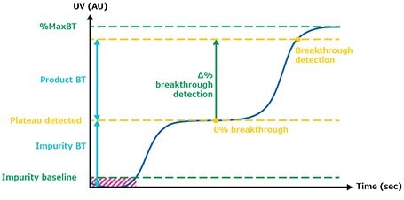
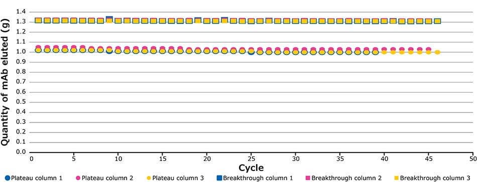
The defined breakthrough (BT) percentage corresponds to the difference between the impurity plateau and maximum UV value of the clarified harvest (Figure 4). Figure 5 illustrates the UV signals of the impurity plateau (dots) and breakthrough (squares) triggering the column switch on the continuous capture system throughout the 139 cycles of the fourth validation run. On the graph, two trends can be observed. The dots indicate a stable absorbance during loading, corresponding to impurities coming out of the column being loaded. The squares on the graph represent the absorbance (of product and impurities) at each cycle and correspond to the switching value absorbance between columns when the defined breakthrough is reached. During this project the switching value used was 60% of the BT. Figure 8 shows an extreme regularity of the level of impurity plateau and breakthrough detections cycle after cycle, with a standard deviation below the accuracy of the sensor (Table 2), demonstrating that performance across different cycles throughout the process was very consistent and comparable.

Figure 4.Breakthrough detection.

Figure 5.Plateau and breakthrough levels during the fourth validation run.
Process Implementation Perspectives
This report exhibits the utility of an automated multi-column capture system for the intensified purification of 1000 L of cell culture harvest containing 3.2 kg of mAb over 55 hours to enable continuous automated manufacturing and lower costs of goods.
Compared to batch mode (1 column), multi-column capture uses much less protein A volume (Figure 6).
Using the MCC system, the volume of protein A required could be reduced by up to 43 times compared to batch mode with a single cycle. The productivity is increased from 30 g.mAb/L.resin/h for batch mode to 40 g.mAb/L.resin/h for 46 cycles with the multi-column capture system. With the MCC system it is possible to purify up to 3000 L of mAb at 4 g/L in 24 hours.

Figure 6.Different scenarios for purifying 3.2 kg of mAbs.
Next generation processing aims to reduce costs by significantly increasing productivity whilst intensifying the process to make it smaller, cheaper, faster or all three. A key bottleneck to productivity improvement has been the primary chromatographic capture step where the volumes are large, and the existing single column technology can only provide a highly intermittent output product stream.
As reported here, multi column chromatography technology considerably reduces the volume of protein A resin required, enables continuous processing, increases efficiency, and reduces cost. This continuous technology, combined with the benefits of single-use equipment, increases mAb productivity, reduces plant footprint, lowers facility investment, improves plant flexibility, and reduces risk to product.
For more information on multi column chromatography and to learn more about our multi column chromatography system, visit our chromatography systems for bioprocessing page.
Acknowledgments
“This work has received funding from the European Union’s Horizon 2020 research and innovation program under grant agreement No. 635557.”
Az olvasás folytatásához jelentkezzen be vagy hozzon létre egy felhasználói fiókot.
Még nem rendelkezik fiókkal?