Electrospinning: Enabling Nanostructured Materials
Dr. Jingwei Xie, Prof. Younan Xia
Material Matters 2008, 3.1, 19.
Introduction
Fibrous nanomaterials are attractive for a range of applications due to their intrinsically high porosities and large surface areas. Electrospinning is a simple, versatile technique for generating nanofibers from a rich variety of materials including polymers, composites, and ceramics.1,2 Figure 1 shows a typical electrospinning setup that consists of three major components: a high-voltage power supply, a spinneret, and an electrically conductive collector. A hypodermic needle and a piece of aluminum foil serve well as the spinneret and collector, respectively. The liquid (a melt or solution) for electrospinning is loaded into a syringe and fed at a specific rate set by a syringe pump. In some cases, a well-controlled environment (e.g., humidity, temperature, and atmosphere) is critical to the operation of electrospinning, especially for the fabrication of ceramic nanofibers.3

Figure 1.Schematic of a typical setup for electrospinning.
In this article, we discuss issues critical to successful application of the electrospinning technique, including control of individual nanofibers to form secondary structures and assembly of nanofibers into 3D architectures. We illustrate a few of the many potential applications of electrospun nanofibers, especially in the area of vascular grafting and tissue engineering.
Mechanism of Nanofiber Formation
Although the setup for electrospinning is extremely simple, the spinning mechanism is rather complicated. The essence of electrospinning is to generate a continuous jet by immobilizing charges on the surface of a liquid droplet. It has recently been resolved that the spinning process is solely a result of whipping rather than splaying of a liquid jet.4,5 The whipping instability originates from the electrostatic interactions between the external electric field and the surface charges on the jet. Stretching and acceleration of the unstable fluid filament, where the liquid phase has to maintain an appropriate viscoelasticity in order to survive the whipping process, results in the formation of fibers with nanoscale diameters. Electrospun fibers are typically several orders in magnitude smaller than those produced using conventional spinning techniques. By optimizing parameters such as: i) the intrinsic properties of the solution including the polarity and surface tension of the solvent, the molecular weight and conformation of the polymer chain, and the viscosity, elasticity, and electrical conductivity of the solution; and ii) the operational conditions such as the strength of electric field, the distance between spinneret and collector, and the feeding rate of the solution, electrospinning is capable of generating fibers as thin as tens of nanometers in diameter.1
Controlling Individual Nanofibers
In the early days, electrospinning was mainly used to prepare polymeric nanofibers, and so far it has been successfully applied to more than 100 types of natural and synthetic polymers.6 Recently, electrospinning was integrated with sol-gel chemistry to generate composite and inorganic nanofibers.3 Polymers, such as poly(vinyl pyrrolidone) (PVP, 437190), poly(vinyl alcohol) (PVA, 341584), or poly(ethylene oxide) (PEO, 189456) can be processed from solutions containing a sol-gel precursor, followed by selective removal of the organic phase via calcination in air. This approach can be applied to essentially any oxide material with an available sol-gel precursor (e.g., a metal alkoxide). Notable examples include: Al2O3, SiO2, TiO2, SnO2, V2O5, ZnO, Co3O4, Nb2O5, MoO3, GeO2, ITO, NiFe2O4, LiCoO2, MgNiO2, and BaTiO3.7–9 With the use of specially designed precursor polymers such as poly(norbornenyldecaborane), the capability of electrospinning has been further extended to fabricate nonoxide ceramic nanofibers such as silicon carbide and boron carbide.10 These inorganic nanofibers are expected to find use in applications related to energy conversion, energy storage, and structural reinforcement.
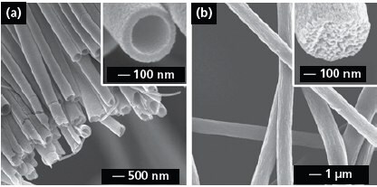
Electrospinning has also been conducted with a spinneret consisting of co-axial or side-by-side capillaries to generate nanofibers with a variety of secondary structures including core-sheath or porous fibers and nanotubes with single or multiple channels.11-16 Figure 2a shows SEM image of TiO2 (anatase) nanotubes that were fabricated by electrospinning with a co-axial spinneret, followed by calcination in air. In a typical process, the inner and outer capillaries were fed with mineral oil and an alcoholic solution containing PVP and Ti(OiPr)4 (205273), respectively. A co-axial jet was formed because the oily and alcoholic phases could not mix during the spinning process. Electrospun fibers can also be made porous by modifying the collection scheme. For example, we have demonstrated the fabrication of highly porous fibers by electrospinning the jet directly into a cryogenic liquid.17Well-defined pores developed on the surface of each fiber as a result of temperature-induced phase separation between the polymer and the solvent and the evaporation of solvent under a freeze-drying condition. Figure 2b shows SEM image of porous poly(styrene) fibers prepared using this method. The inset shows a cross-sectional image of a broken fiber, indicating that the fiber was porous throughout. This approach has been extended to a number of polymers including poly(vinylidene fluoride) (427152), poly(acrylonitrile) (181315), and poly(ε-caprolactone) (181609).

Figure 2.(a) SEM image of a uniaxially aligned array of TiO2 (anatase) nanotubes. Reprinted from Ref. 13 with permission from American Chemical Society. (b) SEM images of polystyrene porous fibers fabricated by electrospinning the jet into a liquid nitrogen bath, followed by drying in vacuo. Reprinted from Ref. 17 with permission from American Chemical Society.
Controlling the Alignment and Assembly of Nanofibers
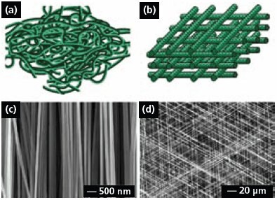
Electrospun fibers are usually deposited on the collector as a non-woven mat, in which the fibers take a completely random orientation (Figure 3a). Several approaches have been developed to organize electrospun fibers into aligned arrays. For example, electrospun fibers can be aligned into a uniaxial array by replacing the single-piece collector with a pair of conductive substrates separated by a void gap.11 In this case, the nanofibers tend to be stretched across the gap oriented perpendicular to the edges of the electrodes. It was also shown that the paired electrodes could be patterned on an insulating substrate such as quartz or polystyrene so the uniaxially aligned fibers could be stacked layer-by-layer into a 3D lattice (Figure 3b). By controlling the electrode pattern and/or the sequence for applying high voltage, it is also possible to generate more complex architectures consisting of well-aligned nanofibers.12
Figure 3c shows SEM image of a uniaxial array of carbon nanofibers that were electrospun from a solution of poly(acrylonitrile) in dimethylformamide, followed by stabilization in air and carbonization. This approach can, in principle, be applied to any electrospinable material since the alignment is mainly determined by the arrangement of electrodes in the collector. Figure 3d shows SEM image of a tri-layered thin film of poly(vinyl pyrrolidone) nanofibers that were deposited across three pairs of electrodes by alternately connecting each pair to the high voltage supply. The nanofibers in each layer were uniaxially aligned, with their long axes rotated by 60 degrees between adjacent layers. Uniaxially aligned nanofibers between two fixed points could also be twisted to form bundles and other types of constructs (e.g., a micrometer-sized yarn by braiding three nanofiber bundles manually).18 In related work, the continuous yarns consisting of aligned nanofibers were further woven into textiles for various applications.19

Figure 3.(a) Schematic of nanofibers with random orientation. (b) Schematic of a 3D lattice of nanofibers. (c) SEM image of a uniaxially aligned array of carbon nanofibers. Reprinted from Ref. 11 with permission from American Chemical Society. (d) SEM image of a layer-by-layer stacked thin film of PVP nanofibers. Reprinted from Ref. 12 with permission from Wiley-VCH.
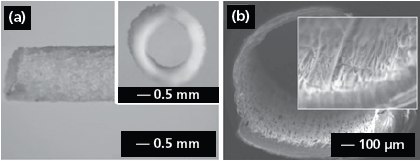
Electrospun nanofibers could also be directly deposited on various objects to obtain nanofiber-based constructs with well-defined and controllable shapes. Figure 4a shows the side view of a poly(propylene carbonate) (PPC, 389021) tube (2 mm in diameter) fabricated by depositing electrospun fibers onto a cylindrical rod, followed by removal of the rod.20 The inset shows a cross-sectional view of the tube. In addition, one can manually process membranes of aligned or randomly oriented nanofibers into various types of constructs after electrospinning: for example, fabrication of a tube by rolling up a fiber membrane or the preparation of discs with controllable diameters by punching a fiber membrane. Figure 4b shows the crosssectional view of a nerve conduit made of aligned fibers containing glial cell line-derived neurotrophic factor (GDNF, G1401).21 The conduit was simply fabricated by rolling up the fiber membrane and suturing the connection site with dichloromethane. More work remains to be done in the future in order to organize electrospun nanofibers into the 3D architectures desirable for a range of applications.

Figure 4.(a) Side and cross-sectional (inset) view of an electrospun PPC tube. Reprinted from Ref. 20 with permission from Blackwell Publishing. (b) Cross-sectional view of a nerve conduit with aligned GDNF-encapsulated fibers. Reprinted from Ref. 21 with permission from Wiley-VCH.
Application in Tissue Engineering
Electrospun nanofibers offer great promise for engineering of artificial skins, muscles, blood vessels (vascular grafts), orthopedic components (bones, cartilages, and ligaments/ tendon), and peripheral/central nervous system components. Non-woven mats of electrospun nanofibers can serve as ideal scaffolds for tissue engineering because they can mimic the extracellular matrices (ECM) in that the architecture of nanofibers is similar to the collagen structure of the ECM – a 3D network of collagen nanofibers 50–500 nm in diameter. Furthermore, electrospun nanofibers have several advantages for tissue regeneration: correct topography (e.g., 3D porosity, nanoscale size, and alignment), encapsulation and local sustained release of growth factors, and surface functionalization (e.g., attachment of functional groups). Materials used for tissue engineering must be biocompatible and notable examples include natural or synthetic biodegradable polymers, biocompatible polymers, and blends with bioactive inorganic materials (e.g. hydroxyapatite 574791).
Electrospun fibers can be used to fabricate artificial blood vessels. Aligned nanofibers of biodegradable poly(l-lactideco- ε-caprolactone) (457639) have been evaluated as a potential scaffold for blood vessel engineering through culturing human coronary artery smooth muscle cells.22In another study, the composition and mechanical properties of a vascular graft scaffold fabricated from blends of Type-I collagen (C3511), elastin, and poly(d, l-lactide-co-glycolide) (531154) were found to be similar to those of native blood vessels and the grafts were biocompatible and did not induce local or systemic toxic effects when implanted in vivo.23 One remaining problem is to achieve sufficient cellular infiltration into the electrospun fibrous matrix. This was partially solved by combining electrospinning and electrospraying to fabricate cell-microintegrated blood vessel constructs — conduits that were highly cellularized with smooth muscle cells (SMCs) in the interior of the walls.24 These conduits were shown to be cytocompatible, strong, and possess compliance values similar to native blood vessels.
Electrospun fibrous scaffolds can be combined with gene therapy and stem cell biology to provide a new route to blood vessel regeneration. For example, a vascular graft has been fabricated by seeding genetically modified autologous mesenchymal stem cell (MSCs) onto a tubular scaffold of electrospun poly(propylene carbonate) and the seeded cells could then be integrated into the microstructure of the graft to form a 3D cellular network.25 In another work, bone marrow MSCs in poly(l-lactic) acid (PLLA, 38534) nanofibrous vascular grafts have been demonstrated to be antithrombogenic in vivo.26 Figure 5a and 5b show confocal micrographs of the human aortic SMCs and bone marrow MSCs seeded on aligned PLLA nanofibers surface. It can be clearly seen that the cellular organization and alignment were similar to that of the native artery. In this study, the aligned PLLA nanofibers were fabricated as a membrane by electrospinning and then rolled up into a tubular graft with the incorporation of marrow MSCs (Figure 5c). Figure 5d shows a photograph where the vascular graft composed of PLLA nanofibers and MSCs was sutured to the common carotid artery (CCA) of a rat. These results demonstrated that nanofibrous scaffolds allowed the remodeling of vascular grafts in both cellular and ECM contents, similar to that of the native artery.

Figure 5.(a, b) Human aortic smooth muscle cells and bone marrow stem cells seeded on thin films of aligned PLLA nanofibers. The actin filaments were stained with FITC-conjugated phalloidin (green), and the nuclei were counterstained using propidium iodide (red). (c) The tubular graft formed by rolling the cell-embedded fibrous membrane. (d) An end-to-end view of the vascular graft sutured to the common carotid artery in a rat.26
Conclusion
The past five years have witnessed tremendous progress in the area of electrospinning. The capabilities of many wellestablished techniques for material processing can be greatly enhanced by combining them with electrospinning. The composition, morphology, and structures of fibers could be further tailored using a number of physical and/or chemical methods. For example, encapsulation has been exploited to provide a simple route to multifunctional nanofibers.27,28 All of these research activities have led to the exploitation of electrospun nanofibers in a broad range of applications. It is expected that research on this technique will become more interdisciplinary in the future. With the involvement of a larger scientific and engineering community, electrospinning will surely become one of the most powerful tools for fabricating nanostructured materials with the broadest range of functionalities and applications.
References
To continue reading please sign in or create an account.
Don't Have An Account?